
CFD Evaluation of Airflow Distribution and Thermal Performance in a Lithium-Ion Battery Pack
This case study presents a Computational Fluid Dynamics (CFD)–based thermal analysis of an air-cooled lithium-ion battery pack. The objective of the study was to evaluate airflow distribution, temperature uniformity, and heat dissipation performance under steady operating conditions.
COMPUTATIONAL FLUID DYNAMICS
Case Study: CFD Simulation of an Air-Cooled Lithium-Ion Battery Pack
Project Overview
Thermal management plays a critical role in ensuring the safety, performance, and service life of lithium-ion battery systems used in electric vehicles and energy storage applications. During charging and discharging, battery cells generate heat due to internal resistance and electrochemical reactions. Inadequate heat removal can lead to temperature non-uniformity, accelerated degradation, and increased safety risks.
This case study presents a Computational Fluid Dynamics (CFD) analysis conducted to evaluate the thermal performance of an air-cooled battery pack. The study focuses on airflow distribution, heat dissipation capability, and temperature uniformity across battery cells under steady operating conditions.
Objectives of the Study
The objectives of this CFD study were:
To evaluate airflow distribution within the battery pack
To predict temperature distribution across battery cells
To identify potential hot spots and regions of inadequate cooling
To assess pressure drop across the cooling flow path
To generate engineering insights for improving battery thermal management design
System Description
The system analyzed consists of a battery module comprising multiple cylindrical lithium-ion cells housed within an enclosure and cooled using forced airflow. Cooling air enters through inlet ducts, flows between the battery cells, and exits through outlet passages.
For the purpose of this study, the battery pack was modeled using a simplified representation, where individual battery cells were treated as homogeneous heat-generating solids. Internal electrochemical behavior, electrical tabs, and busbars were not explicitly modeled, as the primary focus was on pack-level airflow behavior and thermal management effectiveness.
This modeling approach was intentionally selected to capture the dominant thermal and fluid flow characteristics while maintaining computational efficiency consistent with early- to mid-stage design evaluation.
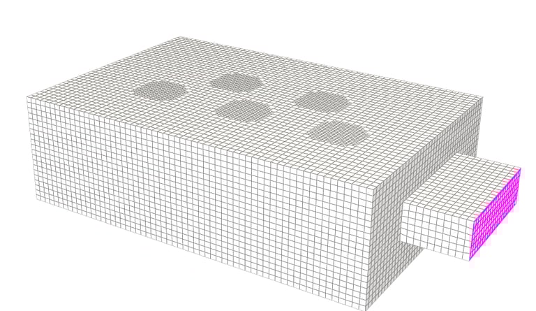
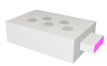
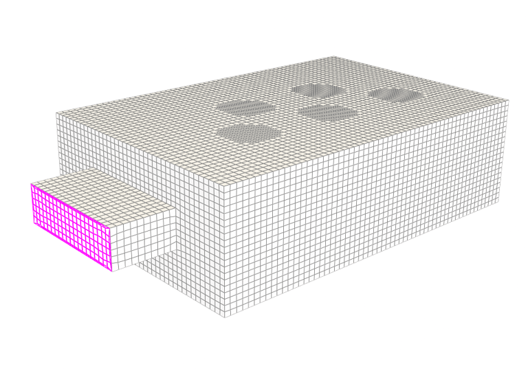
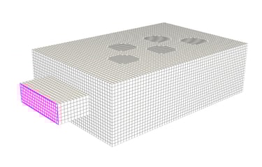
Geometry and Computational Domain
A three-dimensional computational domain was developed to represent both the solid and fluid regions relevant to heat transfer and airflow:
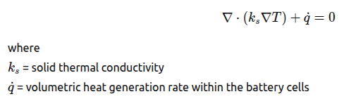
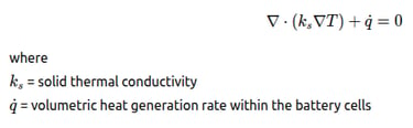
Solid domains representing battery cells with uniform volumetric heat generation
Fluid domains representing airflow passages between cells and within the enclosure
Conjugate interfaces between solid and fluid regions to enable coupled heat transfer
Geometric simplifications were applied to eliminate non-critical details while preserving the flow paths, thermal interfaces, and spatial relationships governing cooling performance.
Material Properties
Material properties were defined to represent typical lithium-ion battery and air characteristics:
Battery cells:
Effective density, specific heat, and thermal conductivity
Uniform volumetric heat generation corresponding to operating conditions
Cooling air:
Incompressible Newtonian fluid
Constant specific heat and thermal conductivity
Temperature-dependent density
These assumptions are appropriate for pack-level thermal evaluation under steady-state operating conditions.
Boundary Conditions
Inlet
Prescribed air velocity corresponding to cooling fan operation
Fixed inlet temperature representing ambient conditions
Outlet
Pressure outlet with atmospheric reference pressure
Walls and Interfaces
No-slip velocity condition at all solid surfaces
Conjugate heat transfer enabled between battery cells and cooling air
All enclosure walls not directly exposed to the cooling flow were assumed adiabatic.
Governing Equations:
Continuity Equation
The conservation of mass for an incompressible or weakly compressible flow is expressed as:
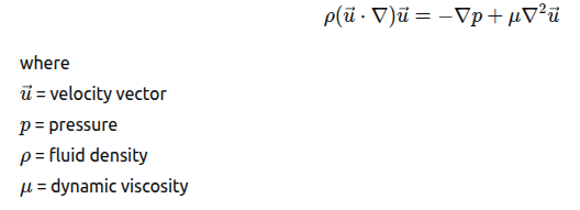
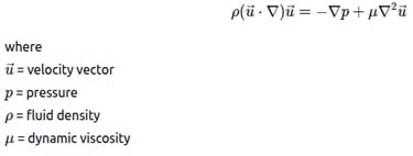
Momentum Conservation (Navier–Stokes Equations)
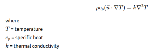
Energy Conservation Equation (Fluid Domain)
Energy Conservation Equation Solid Domain (Battery Cells)
Turbulence Modeling
For turbulent airflow, Reynolds-averaged Navier–Stokes (RANS) equations were solved with an appropriate turbulence closure model suitable for internal duct flows.
Solver Strategy
A steady-state solution strategy was adopted. The coupled momentum and energy equations were solved iteratively until convergence was achieved.
The solution strategy included:
Pressure–velocity coupling for stable flow prediction
Second-order spatial discretization for improved accuracy
Convergence monitoring based on residual reduction
Stabilization of monitored temperatures and velocities
Global energy balance verification
Post-Processing and Key Results
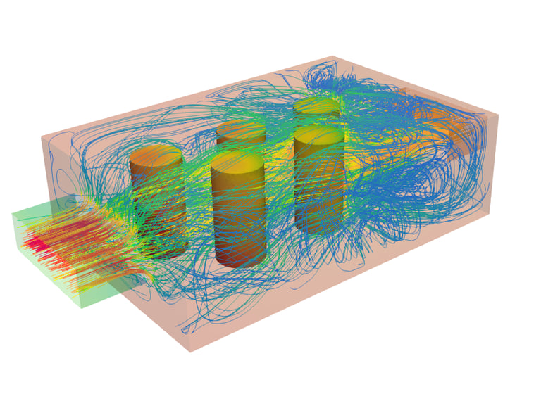
Flow Distribution
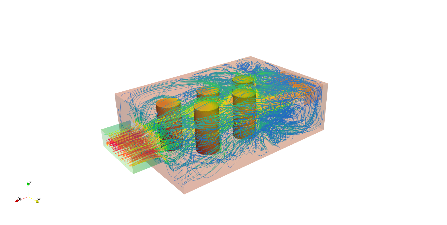
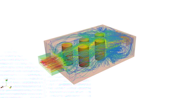
The results indicate non-uniform temperature distribution across the battery pack. Central cells experience higher temperatures due to reduced airflow penetration, while cells closer to primary flow paths remain cooler. The temperature gradients observed emphasize the importance of airflow uniformity in battery thermal management.
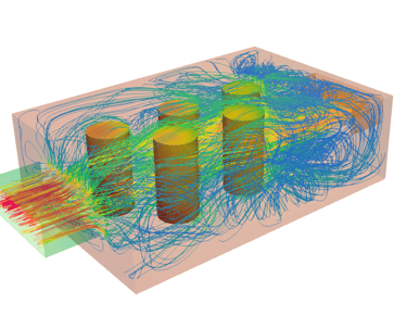
Airflow Characteristics
Velocity contours and streamlines reveal preferential airflow through selected channels, leaving other regions under-cooled. Recirculation zones form downstream of densely packed cell regions, directly contributing to localized hot spots.
Pressure Drop
The predicted pressure drop across the battery module remains within acceptable limits for forced-air cooling systems. However, localized pressure losses increase in narrow flow passages, indicating opportunities for geometry optimization.
Engineering Insights Gained
Key engineering insights derived from this study include:
Cooling effectiveness depends strongly on airflow distribution rather than total flow rate
Hot spots correlate directly with low-velocity and recirculation regions
Minor modifications to channel spacing and inlet distribution can significantly improve temperature uniformity
Thermal performance and pressure drop must be optimized together for an efficient cooling system
Industrial Applications
The findings from this CFD analysis are directly applicable to:
Electric vehicle battery pack thermal design
Stationary energy storage systems
Battery module and power electronics cooling
Early-stage design optimization and feasibility assessment
By selecting a model fidelity aligned with the study objectives, CFD enables reliable thermal performance evaluation while reducing physical prototyping and development time.
Benefits to Industry
The CFD-based thermal analysis presented in this case study delivers several tangible benefits to industry stakeholders involved in battery system design, development, and integration:
Reduced Development Risk: Early identification of thermal hot spots and airflow maldistribution minimizes the likelihood of costly design revisions during later stages of development.
Shorter Design Cycles: Virtual testing through CFD reduces dependence on physical prototypes, accelerating design iteration and decision-making.
Improved Battery Reliability and Safety: Enhanced understanding of temperature distribution helps maintain cells within recommended operating limits, reducing degradation and safety risks.
Optimized Cooling System Design: Insights into pressure drop and airflow behavior enable better sizing of cooling fans and ducts, balancing thermal performance with energy efficiency.
Cost Efficiency: Purpose-driven model fidelity allows engineers to achieve accurate thermal insights without unnecessary computational expense.
Scalability Across Applications: The same CFD methodology can be applied to different battery sizes and configurations, from EV modules to stationary energy storage systems.
Author Linkedin Profile
+91-9879488468
© 2025. All rights reserved.