
CFD Simulation of External Aerodynamics of a Sedan Car
This case study demonstrates a CFD simulation of a sedan car, analyzing airflow behavior, pressure distribution, wake formation, and aerodynamic drag under highway conditions. The study highlights how CFD supports early-stage aerodynamic evaluation and design optimization without reliance on physical testing.
COMPUTATIONAL FLUID DYNAMICS
Case Study: CFD Simulation of External Aerodynamics of a Sedan Car
Project Overview
This case study presents a Computational Fluid Dynamics (CFD) simulation of the external aerodynamics of a sedan car. The analysis evaluates aerodynamic drag and lift, investigates flow separation and wake behavior, and assesses overall aerodynamic performance relevant to vehicle efficiency and stability.
The study demonstrates the application of steady-state, turbulence-resolved external flow analysis commonly used during automotive design and validation stages.
Objectives of the Study
The primary objectives of this CFD analysis are to:
Predict aerodynamic drag (Cd) and lift (Cl) coefficients
Analyze velocity and pressure distribution on vehicle surfaces
Identify flow separation, recirculation, and wake regions
Evaluate external aerodynamic behavior at highway operating conditions
Establish a baseline aerodynamic model for future optimization studies
System Description
The sedan car geometry represents a mid-size passenger vehicle with realistic proportions including bumper, hood, windshield, roof, and trunk. The model also includes simplified representations of side mirrors and underbody as bluff features to capture dominant aerodynamic effects while maintaining mesh predictability.
To minimize boundary interference, the computational domain extends several vehicle lengths upstream, downstream, and laterally. A moving ground boundary condition replicates real road motion effects on external flow.
Geometry and Computational Domain
Full 3D representation of the sedan car exterior
Wind-tunnel–style rectangular domain
Upstream and lateral distances set to mitigate artificial boundary effects
Downstream outlet extended to capture wake development
Material Properties
Working fluid: Air
Fluid assumed incompressible
Standard atmospheric density and viscosity properties used
Boundary Conditions
Inlet: Uniform velocity corresponding to design speed (~90 km/h)
Outlet: Fixed static pressure representing ambient conditions
Vehicle surface: No-slip wall
Ground: Moving wall at vehicle speed
Domain sides & top: Slip boundaries
Governing Equations:
The CFD simulation is based on the three-dimensional, steady-state Reynolds-Averaged Navier–Stokes (RANS) equations for turbulent external flow. Turbulence effects and velocity–pressure coupling are resolved using established numerical models appropriate for bluff-body aerodynamic flows.
Solver Strategy
Steady-state flow solution
Iterative pressure–velocity coupling
Convergence monitored via:
Residual reduction
Stabilization of aerodynamic force coefficients (Cd, Cl)
Post-Processing and Key Results
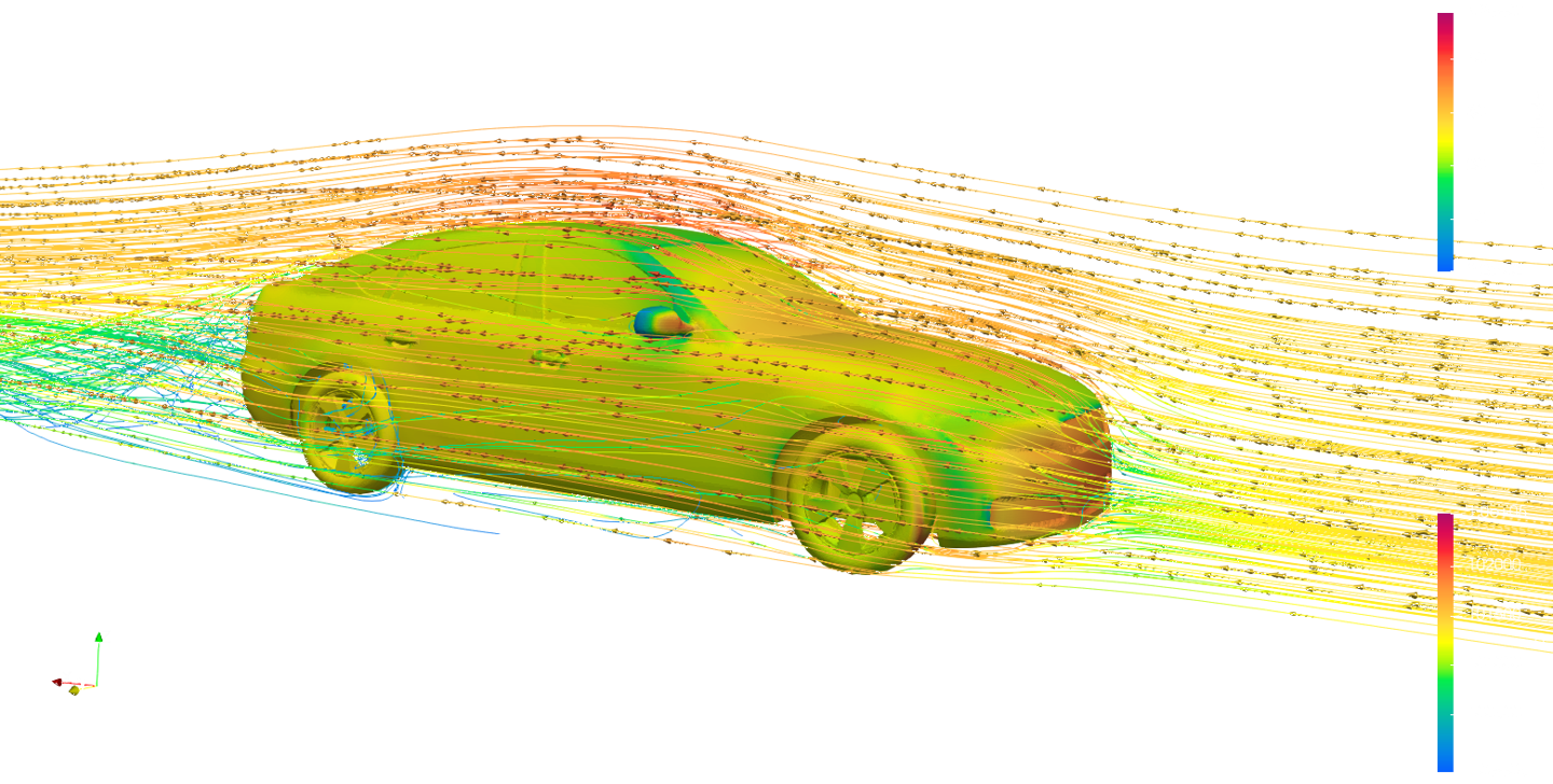
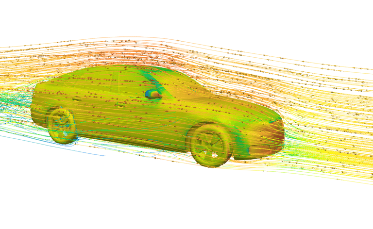
Velocity Distribution
The airflow field around the sedan illustrates:
Acceleration of flow over the hood and roof
High-velocity regions along the rooftop
Strong velocity deficits in the rear wake zone, indicating significant flow separation
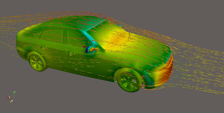
Pressure Distribution
Surface pressure contours reveal:
High static pressure at the front stagnation region
Low-pressure regions ahead of and below the rear deck
Limited pressure recovery on the trunk, contributing to increased drag
Flow Separation and Wake
Flow separation is prominent at:
Rear windshield–trunk junction
Side mirror wake zones
A large recirculation zone develops behind the vehicle, dominating the overall drag behavior.
Aerodynamic Performance
Drag coefficient (Cd): ~0.30 – 0.33
Lift coefficient (Cl): Slightly positive
Dominant drag contribution arises from pressure drag rather than frictional drag
These values provide a baseline performance metric for the sedan body shape under steady flow conditions.
Engineering Insights Gained
The rear geometry significantly influences wake size and drag production.
Pressure drag dominates total aerodynamic resistance.
Separation around bluff features (mirrors, A-pillars) contributes to localized vortex shedding.
External aerodynamic CFD enables early-stage identification of critical design regions prior to physical testing, reducing development time and cost.
Industrial Applications
Passenger car aerodynamic assessment and benchmarking
Fuel consumption and range optimization studies
Baseline aerodynamic performance evaluation before wind-tunnel testing
Concept-level design iteration and comparison
Benefits to Industry
Accurate prediction of drag reduction potential
Insight into flow separation and wake mechanisms
Reduced reliance on physical prototypes during early design
Improved decision-making through visualization of complex flow physics
Author Linkedin Profile

+91-9879488468
© 2025. All rights reserved.