
CFD Simulation of a Heat Recovery Steam Generator (HRSG)
This case study presents a comprehensive Computational Fluid Dynamics (CFD) simulation of a Heat Recovery Steam Generator (HRSG) to evaluate exhaust gas flow behavior, pressure losses, and heat transfer performance under realistic operating conditions.
COMPUTATIONAL FLUID DYNAMICS

Case Study: CFD Simulation of a Heat Recovery Steam Generator (HRSG)
Project Overview
This case study presents a comprehensive Computational Fluid Dynamics (CFD) simulation of a Heat Recovery Steam Generator (HRSG) to evaluate exhaust gas flow behavior, pressure losses, and heat transfer performance under realistic operating conditions.
HRSGs are critical components in combined-cycle power plants and cogeneration facilities, where waste heat from gas turbine exhaust is recovered to generate steam for power production or process use. Non-uniform flow distribution, excessive pressure drop, and thermal stratification inside HRSG ducting and heat exchanger modules can significantly reduce system efficiency and increase operational risks.
The objective of this study is to demonstrate how CFD can be used as a design and optimization tool to assess HRSG performance and identify engineering improvements prior to fabrication or retrofit.
Objectives of the Study
The primary objectives of this CFD analysis are to:
Evaluate exhaust gas flow distribution through the HRSG inlet duct, heat exchanger sections, and outlet stack
Identify flow non-uniformity, recirculation zones, and stagnation regions
Quantify pressure drop across HRSG modules and assess impact on turbine back-pressure
Analyze temperature distribution and thermal stratification
Evaluate heat transfer effectiveness of economizer, evaporator, and superheater sections
Provide design insights and optimization recommendations to improve HRSG thermal performance and reliability
System Description
The Heat Recovery Steam Generator considered in this study consists of the following major sections:
Inlet duct and plenum, guiding exhaust gases from the gas turbine
Economizer, used to preheat feedwater
Evaporator, where water is converted to saturated steam
Superheater, raising steam temperature above saturation
Outlet duct and stack, discharging cooled exhaust gases
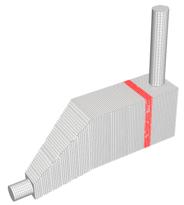
Due to the large scale and complex finned tube geometry, the tube banks are modeled using an equivalent porous media approach, enabling accurate prediction of pressure loss and heat transfer behavior without explicitly resolving individual tubes and fins.
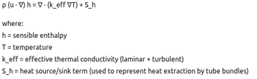
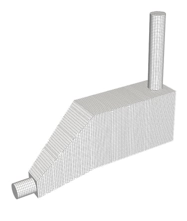
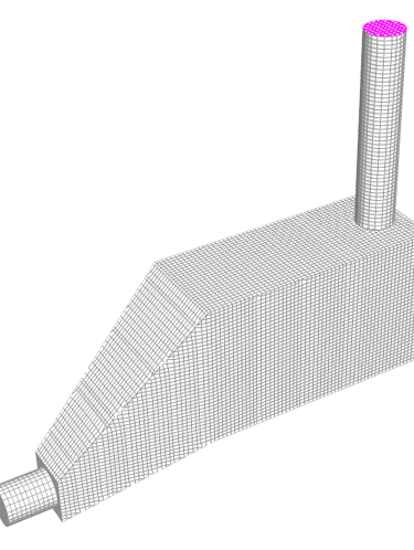
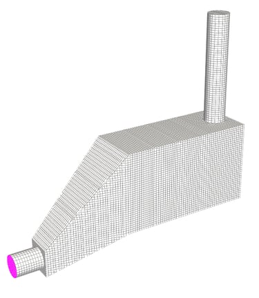
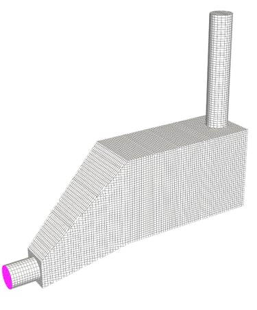
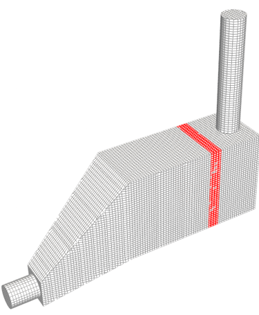
Geometry and Computational Domain
The computational domain includes:
Full 3D representation of the inlet duct and transition sections
Porous regions representing economizer, evaporator, and superheater modules
Outlet stack region up to atmospheric discharge
This approach balances model fidelity and computational efficiency, making it suitable for industrial-scale HRSG simulations.
Material Properties
Working fluid: high-temperature exhaust gas
Temperature-dependent thermophysical properties are used
Heat exchanger regions include volumetric heat sink terms to represent heat extraction by steam/water circuits
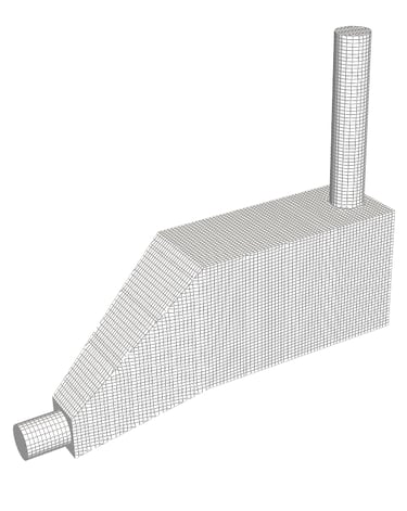
Boundary Conditions
Inlet
Velocity inlet with swirl added profile
Uniform or profiled temperature corresponding to turbine exhaust conditions
Outlet
Fixed static pressure representing stack discharge
Walls
No-slip velocity condition
Adiabatic or specified heat transfer conditions depending on insulation
Porous Zones
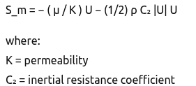
Directional permeability and inertial resistance coefficients
Volumetric heat source/sink terms
Governing Equations:
The CFD simulation is based on the three-dimensional, steady-state Reynolds-Averaged Navier–Stokes (RANS) equations, coupled with the energy equation for turbulent heat transfer. The equations are discretized using the finite volume method.
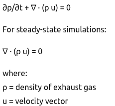
Continuity Equation
The conservation of mass for an incompressible or weakly compressible flow is expressed as:
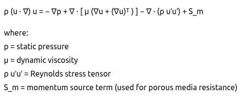
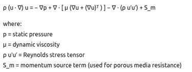
RANS Momentum Conservation Equation
The RANS momentum equation for turbulent flow is given by:
Energy Conservation Equation
The thermal behavior of the HRSG exhaust gas is governed by the energy equation:
Porous Media Modeling for Tube Bundles
The momentum loss in heat exchanger regions is modeled as:
Solver Strategy
Steady-state solution approach
Pressure-velocity coupling using iterative correction
Second-order discretization schemes for convection
Convergence monitored via residual reduction and stabilization of:
Pressure drop
Outlet temperature
Heat transfer rate
Post-Processing and Key Results
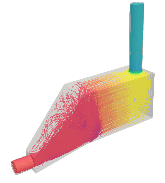
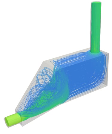
Flow Distribution
Initial simulations revealed a significant "jetting" effect, where the high-velocity exhaust gas concentrated at the center of the first tube bank, leaving stagnant zones at the corners of the duct. This non-uniformity (measured by the RMS velocity deviation) was approximately 25%, exceeding the design target of <10%.
Optimization through Internals
To mitigate this, various configurations of distribution plates and turning vanes were simulated. The CFD results demonstrated that a specific perforated plate porosity (approx. 45-50%) placed in the diffuser section could successfully redistribute the flow.
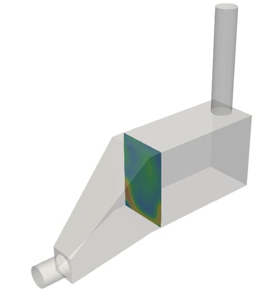
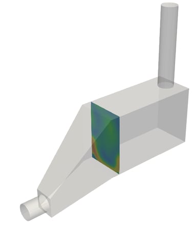
Heat Transfer Performance
Heat transfer effectiveness is directly linked to flow uniformity. Regions with poor velocity distribution exhibit reduced thermal performance.
Engineering Insights Gained
Improve inlet duct geometry or add internal elements (vanes)to enhance flow uniformity
Optimize transition sections to reduce pressure losses
Calibrate porous media coefficients using vendor or test data
Improve exhaust gas distribution to maximize heat recovery
Industrial Applications
Combined Cycle Power Plants
In combined-cycle power plants, HRSGs recover thermal energy from gas turbine exhaust to generate steam for steam turbines. CFD analysis helps in:
Optimizing exhaust gas flow distribution
Reducing turbine back-pressure caused by excessive HRSG pressure drop
Enhancing steam generation efficiency
Cogeneration (CHP) Facilities
In combined heat and power plants, HRSGs supply steam for both electricity generation and process heating. CFD simulations support:
Improved thermal integration between power and process systems
Stable steam production under varying operating loads
Reduced thermal stress due to uneven gas flow
Process Industries
Industries such as oil & gas, petrochemical, chemical, and fertilizer plants use HRSGs for waste heat recovery from fired heaters and process furnaces. CFD assists in:
Evaluating retrofits and capacity upgrades
Identifying maldistribution leading to localized overheating
Ensuring compliance with operational safety margins
Steel, Cement, and Metallurgical Plants
High-temperature exhaust gases from kilns and furnaces are routed through HRSGs to recover energy. CFD is used to:
Handle complex particulate-laden flows
Minimize fouling and erosion-prone regions
Improve long-term operational reliability
Marine and Offshore Applications
HRSGs installed on offshore platforms and large marine vessels benefit from CFD-driven optimization to:
Reduce footprint and weight
Ensure robust performance under variable operating conditions
Improve fuel efficiency and emissions performance
Benefits to Industry
The application of CFD analysis to HRSG design, operation, and optimization delivers tangible technical and commercial benefits across the asset lifecycle.
Improved Thermal Efficiency
Enhanced heat recovery due to uniform exhaust gas distribution
Increased steam generation rates without additional fuel consumption
Reduced Pressure Loss and Operational Costs
Lower gas turbine back-pressure improves overall plant output
Reduced fuel consumption and operating expenditure
Enhanced Equipment Reliability
Identification of thermal stratification and hot spots
Reduced risk of tube overheating, thermal fatigue, and premature failure
Design Optimization and Risk Reduction
Informed decision-making during design and retrofit stages
Fewer physical prototypes and design iterations
Operational Flexibility
Improved HRSG performance under part-load and transient conditions
Better response to changing process demands
Lifecycle Cost Reduction
Lower maintenance requirements
Extended equipment service life
Reduced unplanned shutdowns
Environmental and Regulatory Benefits
Improved energy efficiency reduces greenhouse gas emissions
Supports compliance with environmental and sustainability targets
Author Linkedin Profile


+91-9879488468
© 2025. All rights reserved.