
Discrete Element Method (DEM) Simulation of Hopper for plastic particles
Blog created depicting our CFD (Computational Fluid Dynamics) simulation experience especially for Discrete Element Method (DEM)
COMPUTATIONAL FLUID DYNAMICS
Case Study: Discrete Element Method (DEM) Simulation of Hopper for plastic particles
Project Overview
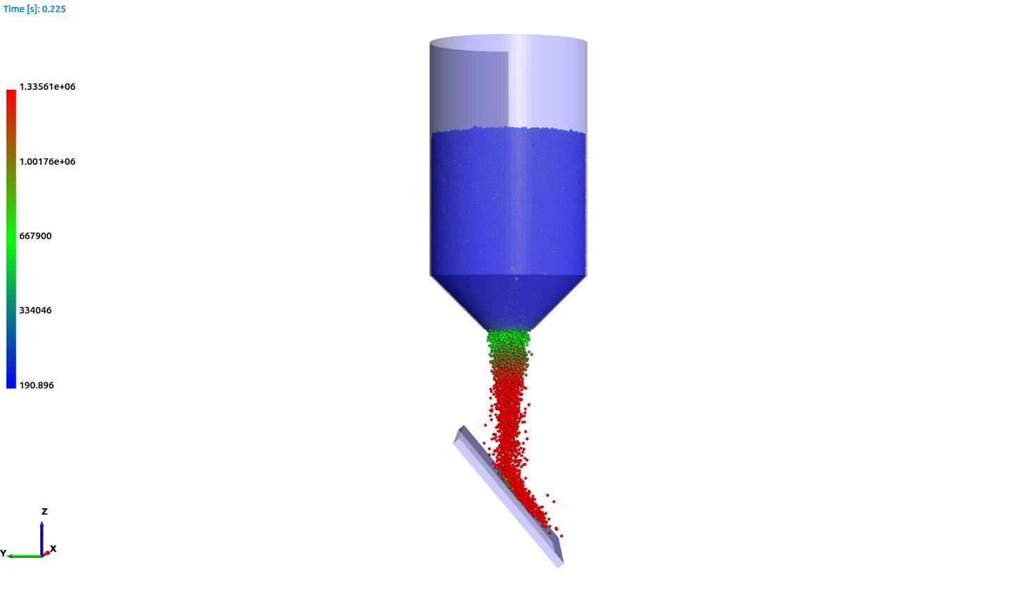
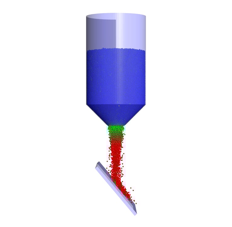
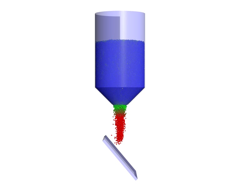
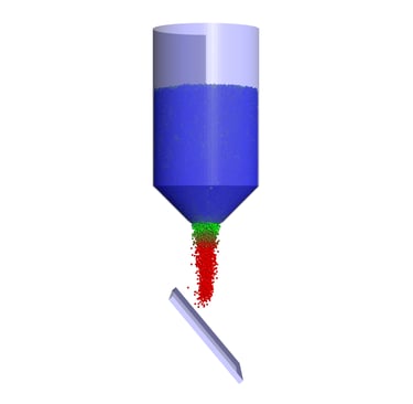
MechSourcing conducted a Discrete Element Method (DEM) Simulation to evaluate the particle velocity and distribution at various angles and find an optimum angle to achieve desired particle flow for further processing.
Objectives of the Study
The primary objective of this case study is to demonstrate the application of Discrete Element Method (DEM) for analysing the flow behaviour, interaction, and segregation of granular materials under realistic operating conditions.
Specifically, the study aims to:
Predict particle trajectories, velocities, and contact forces
Evaluate segregation tendencies
Identify zones of stagnation, arching, or excessive wear
Support equipment design, scale-up, and optimisation
Reduce trial-and-error experimentation and physical prototyping
Geometry and Computational Domain
The reference system modelled in this case study represents a generic industrial granular handling unit, such as:
Hopper System
Key geometric features:
Rigid walls
Defined in CAD and imported into DEM simulation software
Motion can be applied via prescribed angular or linear velocities but for the current simulation gravity based particle flow is considered.
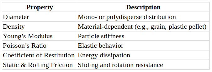
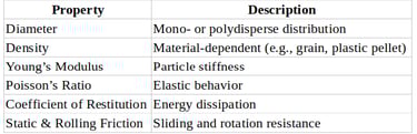
Particle Properties
Each particle is assigned physical and mechanical properties:
Contact Models
Hertz–Mindlin (Nonlinear elastic contact)
Linear spring-dashpot model
Optional cohesive force models (van der Waals / capillary)
Governing Equations:
Translational Motion (Newton’s Second Law)
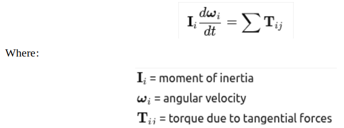
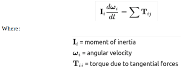
Rotational Motion
Normal Contact Force (Hertz Model)
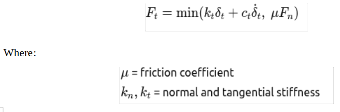
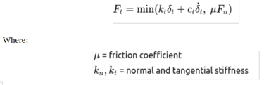
Tangential Contact Force (Mindlin–Deresiewicz)
Simulation Methodology
Step 1: Geometry Import
CAD geometry imported into DEM software
Mesh-free DEM boundaries defined
Step 2: Particle Generation
Particle cloud generated with defined size distribution
Initial packing via gravity settling
Step 3: Contact Model Assignment
Particle–particle and particle–wall models defined
Friction, restitution, and cohesion enabled as required
Step 4: Boundary Conditions
Gravity applied
Rotational speed or translational motion imposed
Time step selected based on Rayleigh criterion
Step 5: Solver Execution
Explicit time integration
Monitoring of kinetic energy and contact stability
Post-Processing and Key Results
Key outputs analyzed:
Particle velocity and acceleration fields
Contact force networks (force chains)
Residence time distribution
Mixing index (Lacey or relative variance)
Wear-prone wall regions
Mass flow rate and discharge uniformity
Engineering Insights Gained
Identification of dead zones and segregation layers
Optimization of rotational speed or feed rate
Prediction of abrasive wear and liner requirements
Validation of scale-up from lab to industrial size
Reduced physical testing costs
Industrial Applications
Food Processing Industry
Powder mixing and blending
Grain handling and milling
Sugar, flour, spice processing
Avoiding segregation and product inconsistency
Plastic and Polymer Processing
Plastic pellet conveying
Hopper and extruder feed optimization
Minimizing pellet breakage and dust formation
Chemical & Pharmaceutical
Tablet coating drums
Catalyst pellet handling
Uniform mixing of active ingredients
Mining & Bulk Solids
Ore flow in chutes and crushers
Stockpile reclaim systems
Wear prediction in transfer points
Benefits to Industry
Design validation before manufacturing
Reduced downtime due to blockages
Improved product quality
Energy-efficient equipment operation
Shorter development cycles
Author Linkedin Profile:
+91-9879488468
© 2025. All rights reserved.