
Pressure Vessel Fatigue Analysis according to ASME Section VIII Div 2
This project outlines our expertise in predicting cyclic life for pressure vessels according to ASME Section VIII Div 2 , Part 5.
FINITE ELEMENT ANALYSIS

Case Study: Pressure Vessel Fatigue Analysis Using Design-By-Analysis
Project Overview
MechSourcing conducted a detailed fatigue analysis of a pressure vessel using the Design-By-Analysis (DBA) approach as per ASME Boiler and Pressure Vessel Code Section VIII, Division 2, Part 5.
Objectives of the Study
The primary objective of this case study is to demonstrate the application of Design-By-Analysis (DBA) methodology for evaluating fatigue damage in pressure vessels subjected to cyclic operating conditions.
Specifically, the study aims to:
Evaluate cyclic stresses due to pressure and temperature fluctuations
Identify fatigue-critical regions such as nozzle-to-shell junctions and weld toes
Quantify alternating stress ranges using FEA-based stress linearization
Estimate fatigue life using ASME-approved S–N curves
Verify compliance with ASME VIII-2 Part 5 acceptance criteria
Support safe operation, life extension, and inspection planning
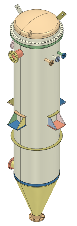
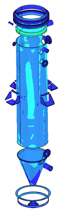
Geometry and Computational Domain
The reference system modelled in this case study represents a generic industrial pressure vessel, commonly used in chemical and process industries.
Pressure Vessel System
Key geometric features:
Cylindrical shell with ellipsoidal heads
Reinforced nozzles with full-penetration welds
Modeled as a full 3D solid domain
CAD geometry imported into FEA software
The model captures geometric stress concentrations critical for fatigue evaluation rather than relying on simplified analytical solutions.
Material Properties
The vessel and nozzles are fabricated from carbon steel pressure vessel material with temperature-dependent properties.
Material inputs include:
Elastic modulus (E)
Poisson’s ratio (ν)
Yield strength as a function of temperature
Coefficient of thermal expansion
Fatigue S–N curve data as per ASME VIII-2
Welded regions are evaluated using structural stress methods consistent with ASME fatigue provisions.
Contact and Structural Modeling
Fully bonded connections between shell, head, and nozzle regions
Weld geometry implicitly represented through stress linearization paths
No contact separation assumed under normal operating conditions
Structural stress approach used to avoid mesh-dependent notch effects
Governing Equations:
Equilibrium (Static / Quasi-Static)
Constitutive Relationship (Linear Elasticity)
Strain–Displacement Relation
Thermal Strain
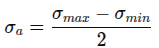
Equivalent Alternating Stress
Fatigue Damage (Miner’s Rule)
Acceptance criterion:
Simulation Methodology
Step 1: Geometry Import
CAD geometry imported into FEA environment
Weld-critical regions identified for stress linearization
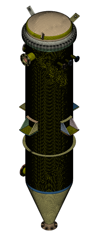
Step 2: Meshing
3D solid elements used throughout
Local mesh refinement near nozzles and shell intersections
Mesh convergence verified for stress accuracy
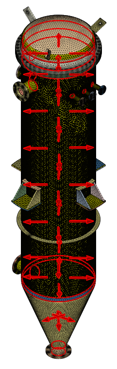
Step 3: Load Definition
Internal pressure cycling (minimum to maximum design pressure)
Step 4: Boundary Conditions
Fixed and displacement boundary conditions were applied
Realistic vessel supports modeled
Operating pressure cases were simulated with different load case options
Step 5: Solver Execution
Linear elastic analysis per ASME requirements
Stress linearization performed along critical paths
Extraction of membrane, bending, and structural stresses
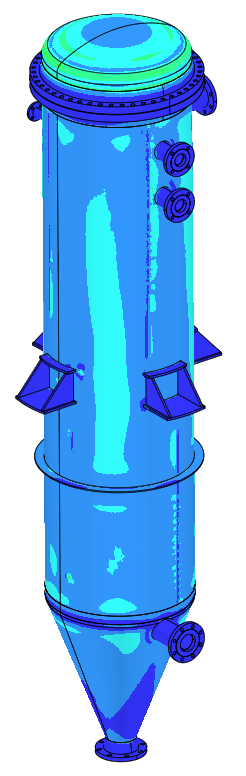
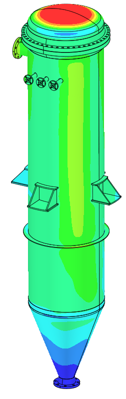
Post-Processing and Key Results
Key outputs analyzed:
Stress intensity and von Mises stress distributions
Structural stress ranges at weld locations
Alternating stress amplitude for fatigue assessment
Number of allowable cycles from ASME S–N curves
Cumulative fatigue damage index
Results confirmed that all evaluated locations satisfied ASME VIII-2 fatigue acceptance criteria for the specified service life.
Engineering Insights Gained
Nozzle-to-shell junctions govern fatigue life
Thermal transients significantly influence alternating stress magnitude
Design-By-Analysis provides higher confidence than Design-By-Rule for cyclic service
Structural stress approach avoids mesh-dependent fatigue errors
Fatigue damage well below allowable limits for intended operating cycles
Industrial Applications
Oil & Gas Industry
Pressure vessels in cyclic separator and compressor service
Thermal fatigue assessment during frequent startups
Chemical & Process Industry
Reactors and columns subjected to batch operation
Fatigue evaluation of nozzle connections
Power & Energy
Heat recovery vessels and drums
Thermal cycling due to load variation
Hydrogen & High-Pressure Equipment
Life assessment of vessels under pressure cycling
Support for life extension and rerating studies
Benefits to Industry
Code-compliant fatigue life assessment
Early identification of fatigue-critical locations
Reduced risk of in-service cracking
Optimized inspection and maintenance planning
Extended equipment life with engineering justification
Reduced conservatism compared to rule-based design
Author Linkedin Profile


+91-9879488468
© 2025. All rights reserved.