
CFD Simulation and Performance Optimization of a Shell-and-Tube Heat Exchanger
This case study presents a detailed 3D CFD analysis of a shell-and-tube heat exchanger to evaluate flow distribution, temperature profiles, pressure drop, and overall thermal effectiveness. The study investigates the influence of baffle configuration on shell-side turbulence, heat transfer enhancement, and hydraulic performance under realistic operating conditions.
COMPUTATIONAL FLUID DYNAMICS
Case Study: CFD Simulation and Performance Optimization of a Shell-and-Tube Heat Exchanger
Project Overview
Shell-and-tube heat exchangers are critical thermal components widely used in oil & gas, power generation, chemical processing, HVAC, and refrigeration industries. Their thermal efficiency and hydraulic performance directly influence energy consumption, operating cost, and system reliability.
This project involved a high-fidelity Computational Fluid Dynamics (CFD) simulation of a shell-and-tube heat exchanger to evaluate internal flow distribution, temperature fields, pressure drop characteristics, and overall heat transfer performance. The study aimed to identify design improvements through detailed thermofluid analysis under realistic operating conditions.
Objectives of the Study
The objectives of this CFD study were:
Develop a full 3D CFD model of a shell-and-tube heat exchanger.
Evaluate temperature distribution and heat transfer rate between hot and cold fluids.
Analyze shell-side flow distribution and identify recirculation or dead zones.
Quantify pressure drop on both shell and tube sides.
Assess the impact of baffle spacing on thermal performance.
Provide engineering recommendations for design optimization.
System Description
The analyzed system is a single-pass shell-and-tube heat exchanger with the following configuration:
Cylindrical shell housing a bundle of straight tubes
Segmental baffles to direct shell-side flow
Counter-flow heat exchange arrangement
Single tube-side pass with uniform inlet distribution
Hot fluid flows through the tubes, while cold fluid flows on the shell side across the tube bundle. Baffles are installed to enhance mixing and improve heat transfer.
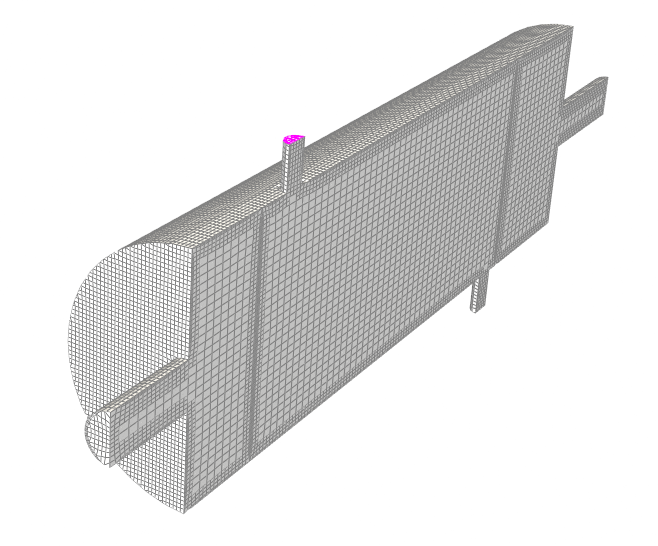
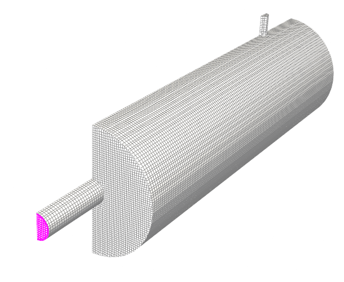
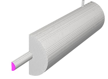
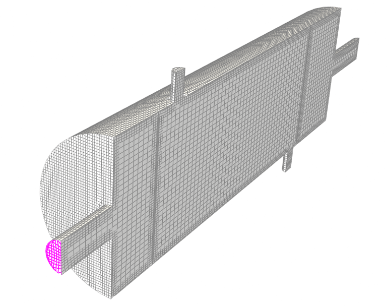
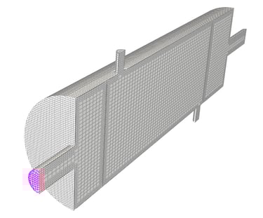
Geometry and Computational Domain
The 3D computational domain included:
Shell enclosure
Tube bundle (modeled explicitly)
Segmental baffles
Inlet and outlet nozzles
Fluid domains for both shell and tube sides
Key modeling considerations:
Full geometry was used instead of symmetry to capture realistic cross-flow behavior.
Fine mesh refinement near tube walls and baffle edges.
Inflation layers applied to accurately resolve thermal and velocity boundary layers.
Grid independence study performed to ensure numerical accuracy.
Material Properties
Tube Side (Hot Fluid):
Water at elevated temperature
Density: Temperature-dependent
Specific heat capacity: Constant average value
Thermal conductivity: Temperature-dependent
Shell Side (Cold Fluid):
Water at lower inlet temperature
Temperature-dependent viscosity and thermal properties
Solid Regions (if conjugate heat transfer considered):
Carbon steel tubes
Thermal conductivity specified based on standard material data
Temperature-dependent fluid properties were incorporated for improved accuracy.
Boundary Conditions
Tube Side
Inlet: Mass flow rate specified
Inlet temperature: High temperature (hot fluid)
Outlet: Pressure outlet condition
Shell Side
Inlet: Mass flow rate specified
Inlet temperature: Lower temperature (cold fluid)
Outlet: Pressure outlet condition
Walls
No-slip boundary condition
Conjugate heat transfer at tube walls
Adiabatic outer shell (insulated assumption)
Operating conditions were selected to represent realistic industrial duty.
Governing Equations:
Continuity Equation
The simulation solved the steady-state, three-dimensional Reynolds-Averaged Navier–Stokes (RANS) equations:
Continuity Equation
Momentum Equations
Energy Equation
Turbulence was modeled using a two-equation turbulence model appropriate for internal turbulent flow.
Heat transfer between fluids was captured through conjugate heat transfer modeling, ensuring accurate prediction of wall temperature gradients and thermal flux.
Solver Strategy
Steady-state pressure-based solver
Coupled pressure-velocity approach
Second-order discretization schemes for improved accuracy
Turbulence model with enhanced wall treatment
Convergence criteria:
Residuals below 10⁻⁶ for energy
Stable heat transfer rate and pressure drop values
Monitors set for:
Total heat transfer rate
Outlet temperatures
Shell-side pressure drop
Tube-side pressure drop
A mesh independence study ensured solution reliability.
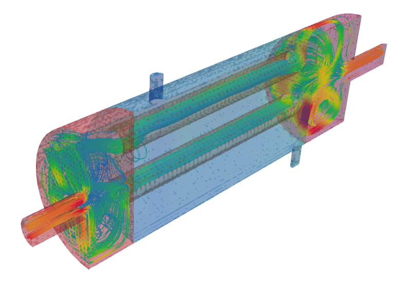
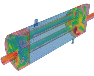
Post-Processing and Key Results
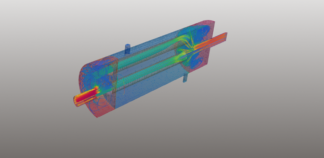
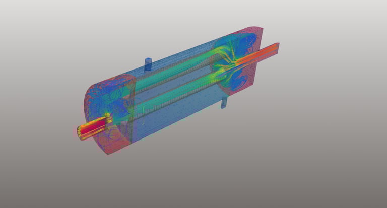
Temperature Distribution
Smooth temperature gradient along tube length.
Enhanced temperature mixing observed downstream of baffles.
Effective counter-flow thermal performance achieved.
Velocity Profiles
High velocity regions near baffle windows.
Controlled cross-flow across tube bundle.
Minor recirculation zones detected near shell walls.
Pressure Drop
Shell-side pressure drop increased with reduced baffle spacing.
Tube-side pressure drop remained within acceptable operational limits.
Trade-off identified between thermal enhancement and pumping power.
Heat Transfer Performance
Overall heat transfer coefficient calculated.
Thermal effectiveness improved with optimized baffle spacing.
Improved shell-side turbulence increased convective heat transfer coefficient.
Engineering Insights Gained
Baffle spacing significantly influences both heat transfer rate and pressure drop.
Uniform shell-side distribution improves exchanger effectiveness.
Excessive baffle restriction increases hydraulic penalties.
CFD reveals localized stagnant regions that cannot be easily detected with empirical methods.
Optimized design achieves a balance between energy efficiency and pumping cost.
The study provided clear visualization of complex flow structures inside the exchanger, enabling data-driven design refinement.
Industrial Applications
This analysis methodology is applicable to:
Oil & Gas process heat exchangers
Power plant condensers and coolers
Chemical process heat recovery systems
HVAC chiller systems
Pharmaceutical process equipment
Food and beverage thermal processing units
Benefits to Industry
Reduced design uncertainty
Improved thermal efficiency
Lower operational energy costs
Optimized pumping power requirements
Faster design validation compared to experimental testing
Reduced prototype development cost
Enhanced reliability and performance prediction
By leveraging high-fidelity CFD modeling, industries can optimize shell-and-tube heat exchanger performance early in the design stage, reducing lifecycle costs and improving system efficiency.
Author Linkedin Profile
+91-9879488468
© 2025. All rights reserved.