
Seismic Analysis of a Gate Valve Using Finite Element Analysis
Discover how seismic loads impact critical piping components through a gate valve seismic analysis using FEA. This study applies ASCE seismic loading with ASME-based stress evaluation, aligned with API valve design intent, to verify structural integrity under earthquake conditions. A practical reference for engineers designing reliable piping systems in seismic regions.
FINITE ELEMENT ANALYSIS

Case Study: Seismic Analysis of a Gate Valve Using Finite Element Analysis
Project Overview
This project presents a detailed seismic analysis of an industrial gate valve subject to earthquake-induced inertial loads. Seismic loads were defined in accordance with ASCE 7 seismic provisions, and structural response was evaluated using finite element analysis (FEA). The valve design intent and pressure boundary integrity are referenced to applicable API valve standards, while stress acceptance and load combinations follow ASME piping and structural criteria.
Objectives of the Study
The primary objectives of this case study are to:
Define and apply seismic inertial loads on the gate valve assembly
Evaluate stresses and structural response under seismic load cases
Identify critical stress and deformation regions
Verify structural integrity against allowable limits
Support design decisions for valve qualification in seismically active regions
Governing Codes and Standards
The following codes and standards were referenced in this analysis:
ASCE 7 – Minimum Design Loads and Associated Criteria for Buildings and Other Structures
Provides seismic acceleration definitions, load combinations, and equivalent static load methodology.ASME B31.3 / ASME Stress Criteria
Governs stress evaluation and acceptance criteria for piping components including valves under dynamic loads.API 6D – Specification for Pipeline Valves
Defines the design, material, and performance requirements for the gate valve.
Note: API standards do not explicitly prescribe seismic load calculation methods. Seismic loading is defined using ASCE 7, and structural evaluation is performed with ASME criteria while ensuring consistency with API valve design intent.
Geometry
Gate Valve Assembly
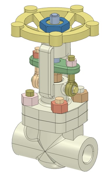
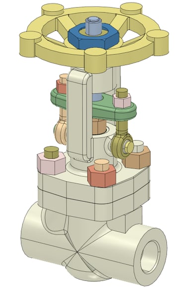
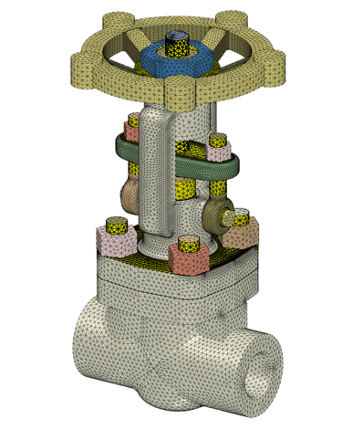
The finite element model represents the full 3D geometry of the gate valve including:
Valve body and bonnet
Gate disc and stem assembly
Flanged end connections
Internal seating components
CAD geometry was imported directly into the FEA environment, capturing critical features influencing stress distribution under dynamic loading.
Material Properties
Material properties used in the model include:
Elastic modulus (E)
Poisson’s ratio (ν)
Density (ρ)
Allowable stress limits based on relevant ASME criteria
These properties were defined for each component to ensure accurate stress and mass representation under seismic excitation.
Contact and Structural Modeling
Bonded contacts applied between mating surfaces
Flange and joint interfaces modeled to represent realistic stiffness
Local mesh refinement at stress concentration regions
Constraints to simulate piping support and anchorage conditions
Governing Equations:
Equivalent static seismic forces were derived using the inertial force relationship:
F = m x a
Where:
F = Seismic inertial force
m = Mass of the component
a = Design seismic acceleration per ASCE 7
Simulation Methodology
Step 1: Geometry Import
Valve CAD model imported into FEA software
Symmetry and boundary conditions identified as applicable
Mass properties and critical load application points defined
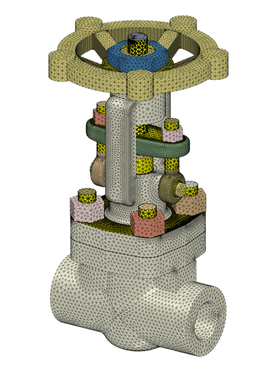
Step 2: Meshing
Solid 3D elements used for all major components
Local mesh refinement at high stress regions
Mesh convergence verified for global and local stress accuracy
Step 3: Load Definition
Seismic inertial forces applied as body accelerations
Independent seismic load cases for horizontal and vertical directions
Equivalent static seismic loads applied per ASCE 7 methodology
Step 4: Boundary Conditions
Constraints applied to represent flange connection stiffness
Loads applied independently and in critical combinations
Support and anchor conditions simulated realistically
Step 5: Solver Execution
Linear static analysis performed for each load case
Reaction forces and stress distributions extracted
Post-Processing and Key Results
Key outputs analyzed include:
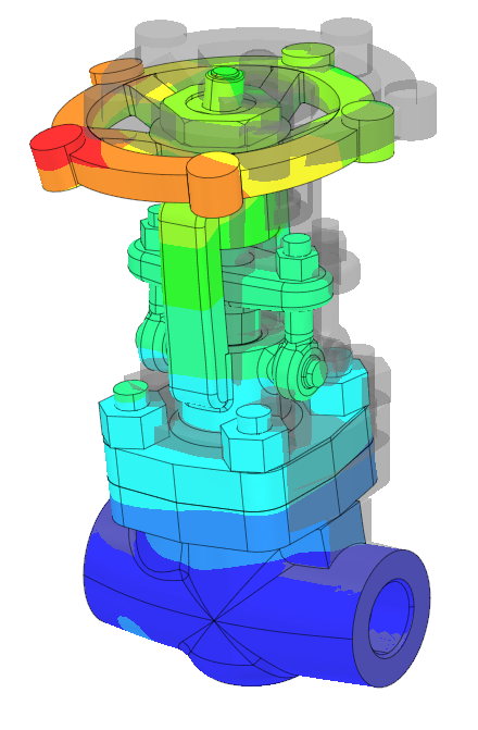
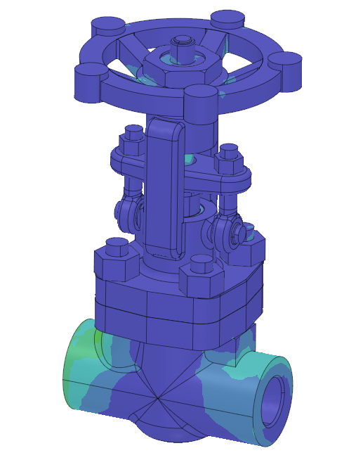
von Mises stress distributions across the valve assembly
Identification of maximum stress regions, particularly at flanged connections and bonnet transitions
Total displacements and deformation contours
Reaction forces at support/flange interfaces
The analysis showed that seismic inertial loads produced elevated stresses at flange-body interfaces, but all calculated stresses remained within allowable limits defined by applicable ASME stress criteria.
Engineering Insights Gained
Horizontal seismic loads generally govern stress demand in the valve body
Flanged connection regions require careful consideration for load transfer
Equivalent static seismic method provides conservative and practical evaluation
API valve design intent can be successfully integrated with ASCE and ASME-based seismic evaluation
Industrial Applications
Industrial Gate Valves in Seismic Zones
Seismic analysis using FEA is essential for industrial valves installed in regions with significant earthquake hazard. The defined seismic load cases ensure that valve bodies, bonnets, and flanged connections maintain structural integrity and operability under seismic excitation.
Piping Systems in Process Industries
Valves often represent significant mass and stress concentrations in piping networks. Seismic evaluation of valves helps ensure overall system safety and compliance with process industry standards.
Power Generation and Petrochemical Facilities
Valves used in critical service lines in power plants and petrochemical facilities may be subjected to seismic loads. FEA-based seismic qualification allows verification without costly prototypes.
Benefits to Industry
Code-aligned structural assessment
Identification of critical transport load conditions
Design guidance for load path reinforcement
Reduced risk of in-service failure during transit
Author Linkedin Profile

+91-9879488468
© 2025. All rights reserved.